Sunday, April 26, 2020

Design Update - Week 14

Goddamn springs, dude.

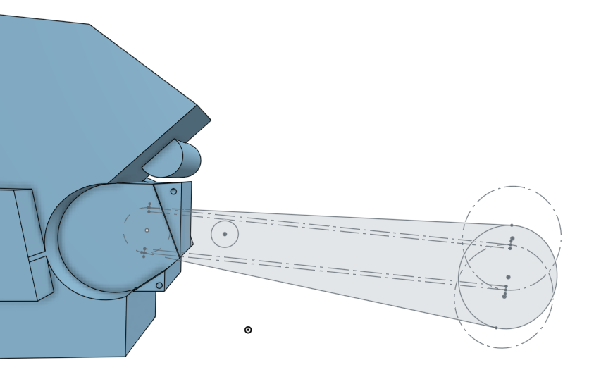
So, I get bored of the math, I start doing some actual chassis modeling, and I happen upon the classic "where the fuck am I putting the shock" conundrum.

And then, I have what can only be described as a total existential catastrophe. What kind of bike do I really want this to be? Why am I building it? Why do I ride motorcycles at all? Why is everything so goddamn complicated always?

Let's back up a bit, and see if I can explain without being dizzingly circular.

Springs

Springs hold up the meat of your motorcycle (and you, you goddamn meatsack). The wheels and suspension bits sit on the tires, but the "suspended mass" is supported by the spring forces. What you end up with is two spring-mass systems (front and rear) that react to bumps, dips, and cornering forces. 

How hard the spring actually pushes down on the suspension (using the contact patch of the tire as a consistent reference point) is called the wheel rate.
Mostly, springs don't push directly on the wheel, they act through suspension (in a telescopic fork they do basically act directly on the wheel, but that's boring and stupid). Because you can play all sorts of games with leverages and links, you can make the spring's effect on the suspension change as the suspension moves - make it progressive (increasing) digressive (decreasing) or linear (constant).

When you mount a shock directly between swingarm and frame, you basically only have "linear" as an option. Yes, the shock swings slightly, so you can make it a bit progressive or digressive, but basically it's just a lever, and levers don't really change shape. It's simple, it's elegant, it's lightweight. ALL THINGS I REALLY WANTED FOR THIS BIKE. Less bearings, less parts, less math, less fabricating, less bullshit. Oh god how I wanted to make a direct-mount shock work. I want to get on something bare-bones and rip across the country, eating squids on sportbikes and basking in the glory of one less bolt to vibrate loose.

So then, you ask yourself, why do all sportbikes (the bikes designed by the industry's tightest-sphincter weight nazis), spend all those precious kilograms on linkages? Marketing? Keeping the bike from bottoming out when Rufus BigBones is riding pillion with his girlfriend on her bike? Below is L3na (my Gixxer, left) and a direct-mount shock comparison. Same spring rate, same shock stroke, same wheel travel, same sag setting.


The wheel rates of the two designs are plotted below. Note how the vertical scales aren't the same, but I've added some numerical tags to help the comparison


Springs store energy. Size X spring = size X energy bucket. Suspension linkages don't perform any magic - the bump that would bottom out the direct-link would also bottom out the progressive link, above. Linkages change when that energy is stored.

The black line in the plots above is static sag - where the suspension would sit in a straight line while coasting. If you notice, L3na's wheel rate is 28.3N/mm, where the direct-link is 30.7. That means every bump feels 11% harsher on the direct link.

Next, look at 60mm wheel displacement - both bikes have a 31.1N/mm rate. Here, mid-corner (where the cornering forces compress the suspension) a bump feels the same on both bikes.

Beyond 60mm, L3na's suspension feels harsher. At 80mm of displacement, L3na is 34.4N/mm to the direct's is 31.8, or another 11%.

The magic here is this: where the rear wheel spends most of its time - between upright and mid-corner - L3na's suspension is softer (being nicer to the rider, and more importantly to the tire) while still being able to handle as big a hit without bottoming as the direct link. Remember - being nicer to the tire means more grip & and less wear, making the bike faster.

The harsher bottom-half of L3na's suspension would only be felt during larger hits when the bike is more upright, which is less important for tire and rider abuse (sorry, Rufus...).

Was this revelation about progressive linkages enough to make me abandon my hankering for direct-link? Nope. Let's continue.

Every mass bouncing on a spring has a natural frequency, where the duo will bounce at a certain rate. Stiffer the spring/lighter the mass, the faster the rate. When applied to vehicles, this is called ride frequency. Using ride frequency is a simple way to describe how stiff the suspension feels (from the springs, anyway - damper settings also change the hard/squishy feeling, but damper settings are the cart behind the spring's horse). Ride frequency is just a simple math tool that lets you ignore how much the bike actually weighs or what the spring rates actually are, and just focus on how they act. Ride frequency is also an easy way to look at how the two ends of the bike behave relative to each other.

The concept of ride frequency/suspension frequency is easy to google - and there's tons of information on what different frequency ranges work for different types of cars. Unshockingly, fucking nothing about bikes. One thing that is often talked about is the ride frequency difference front and rear - how you usually want the rear frequency to be higher (you want the rear to bounce faster) so that (making the naive assumption that the vehicle is moving forward...) by the time the dampers have stopped a bounce, the front and rear of the vehicle are bouncing in unison. This makes the vehicle feel planted, especially in corners.

So that ^ ended up being the key to my crisis, but we'll get to that.

I need to make the front and rear ride frequencies match each other. Seems simple enough - just pick the correct springs.

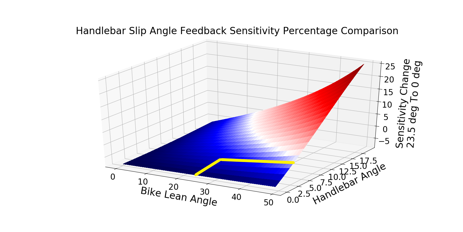
Oh crap, it's not just springs. Ride frequency comes from wheel rate, not spring rate. Well, I know the wheel rate on a telescopic fork is constant, but what happens on my sweet Hossack front end? Here's that wheel rate plot:


Ugh, damnit. It's progressive. If I match a direct-link rear with mid-corner Hossack front, the bike might suck at low lean angles. If I match it with upright Hossack, the bike might suck at high lean angles.

How to fix this? Make the rear progressive, too. If the front and rear wheel rates increase at the same time, both ride frequencies rise in unison, so the bump response stays the same. 

Turns out, I can use the stock "dogbone" pullrod from a GSXR-600 with a different setup that gives me good curves, decent packaging, and a lightweight link:


Also, here's the other three suspensions I tried, including that direct-mount job:


Looks like I have to make the rear a link suspension. Well, there goes 3 bearings, 4 bolts, 10 hours of fabrication, and 2kg. Nuts.

To figure out what the ride frequency actually should be required I (again) steal Suzuki's work by reverse-engineering L3na and Suzi. I measured up the links and springs to find the wheel rates, and estimated the rear suspended mass to find ride frequency at different suspension positions.

Rear:
Suzi, My GS500 = 2.1Hz @ 0* lean
L3na, My GSX-R600 = 2.6Hz @ 0* lean

Front:Suzi = 0.7Hz
L3na = 0.7Hz

So...what gives? Why are the front ride frequencies sooooooo low? Uh, telescopic forks? As far as I can tell, the springs in the fork are chosen A) so you don't bottom under steady-state braking, and B) so the trail is appropriate mid-corner. Looks like that just requires very low wheel rates. No, I didn't forget to count both the left and right springs in the forks. 

Also, now we know regular motorbikes have ride frequency differences front-to-rear that are totally out to lunch! I can abandon my progressive link and do whatever I want!

Also, no. I decided this is going to be the motorcycle I deserve, even if it's not the one I want to build. The matched frequency works for cars, and now my hands are not tied by telescopic forks. I'm going to make the front ride frequency ~90% of the rear. In Hossack we trust, I guess.

I'm going to aim for ~2.3Hz for a ride frequency in the rear. I figure splitting the difference between Suzi and L3na is a good target. Also, my hands are a bit tied by my choice in dampers.

Dampers

I'm using stock '11-'20 GSX-R600 dampers. Why? Because I already had one handy (L3na got K-tech for her birthday this year) and because they are about the right spec for the mathbike.

Damping, generally, is matched to the spring rate and ride frequency of the motorcycle in question. If I choose similar springs and ride frequency (meaning similar suspension travel as well) to the GSXR, the dampers should work. They are somewhat adjustable, and I've found the stock GSXR damping pretty livable on the street. I found a company that has a pretty wide range of springs for the shock, too, so if I get buried by harsh ride I can try to dig myself out with different springs.

But AJ, what about progressive springs + direct mount shock? Doesn't that do what you want it to?

Maybe!

First issue is that there's only one progressive spring for this GSXR shock, an 83-113N/mm unit from EPM. I don't really want to be trapped by a single spring option for something as much of a hack as this mathbike.

Second, the dampers are built for linear springs - no matter how compressed the spring is, one more newton of force will compress the spring the same distance. If the spring "fought" the shock harder at one end of stroke than the other, the shock might be underdamped at full bump and overdamped at full droop. KTM uses direct-mount shocks with progressive springs, but their WP dampers also change damping rate during their travel to match the changing spring rate. Good on you for over-engineering that one, KTM (full disclosure, Eyegore rides KTMs exclusively...)

Monday, February 24, 2020

Design Update - Week 6

Well, I got a little lost in the math on this one...

Good thing it's called the "MathBike."

Anyway, there I was, staring at the Slipknot poster behind my computer screens, imagining what a bike with anti-dive would be like to ride. I kept trying to reconcile what the bike would do on corner-entry with what I had seen on the anti-dive plots I've generated, and realized it wasn't a simple interaction. 

Anti-dive changes with front suspension position, and cornering forces change how high the bike rides. Therfore, anti-dive percentage changes with lean angle, but braking usually also changes with lean angle...

Would the front of the bike feel jacked-up, then plummet mid-corner when I relaxed off the trail braking? Would the anti-dive go weak because of the cornering forces, making the front pop back up when I was done trail braking? Also, the goddamn springs! They push back harder lower in the travel! Does that make most of this a moot point?

Trying to compare it in my head to telescopic forks, another thought occurred to me - knowing what the front suspension does on corner-entry is probably important, but what the hell happens to trail? Steering is trail!

Anti-dive or not, the rear of the bike is going to lift, making the rake steeper and reducing trail. But my Hossack linkages increase trail as I use up travel, does that counteract this behavior? More than counteract? Less? What happens when the rear suspension relaxes back down after braking in a corner?

And so I bit a bag of bullets and wrote, by far, my biggest piece of software ever.

My program eats up bike parameters like wheelbase, nonsuspended mass, CoG location and wheel radii; behaviors like anti-squat, wheelrate, anti-dive and rake change; and inputs like lean angle and accel/decel G, and spits out where both ends of the suspension are, and what the trail is.

Also, I have to gloat a bit about this - it solves these parameters iteratively, which eliminates a big source of error. You hit the brakes, and weight transfers according to the CoG height. But, this weight transfer lifts one end of the bike and lowers the other, changing the CoG height, and affecting the original weight transfer! My program solves this same situation again and again until the resulting suspension positions stop changing, signifying it's arrived at the correct answer. I think that's pretty neat.

Anyway, I took this program and fed it combinations of lean angle and braking that simulated different types of corner entry, and used that to compare the behavior of L3na (my gixxer track bike) to a particular Hossack setup I was playing with.


Let's explain this nonsense a little bit more - 

Bold traces - Front suspension position
Faint traces - Trail

Red traces - L3na (my gixxer6)
Blue traces - Mathbike

*The bottom two plots are different, and show how the anti-dive behavior (left axis) and trail (right axis) changes with front suspension position (x-axis). Interestingly, a telescopic fork actually has negative anti-dive, because both load transfer and braking G compress the forks.

The other plots show the behavior of both bikes during different corner entry situations (with the exception of the "Brake grabs" plot, which literally just shows what the front does when you yank on the brakes in a straight line with increasing brutality).

I've normalized the two bikes by making the wheelrates the same (basically, the tires on both bikes feel the springs are identical), and the trail the same while coasting in a straight line. This just makes them easier to compare for now.

You can see that in most cases, the red bike (telescopic) dives hard, and relaxes upwards to a steady position mid-corner. The blue bike (hossack) sometimes relaxes upwards, sometimes downwards, and sometimes approaches gently in a flat line to this same mid-corner position. 

As far as I can tell, the slower the front of the bike reaches the mid-corner "relaxed" position, the better the front suspension will feel on entry (meaning nothing sudden will happen when I let off the brakes). Interestingly, there is one situation (third plot on the left) where the telescopic bike (red) is already at steady-state for a bit before the hossack bike is, meaning it might feel better? In general, however, it looks like corner-entry suspension movement is better on the hossack.

Trail is an entirely different issue, and one I'm probably going to have to fight a bit on the hossack design.

You can see that, in all cases, there is a TON more trail on the hossack bike mid-corner (~15% more) which is probably going to make the thing a bear at the vertex. I need to adjust the linkage so that doesn't happen.

(Quick aside - people refer to the part of the corner where you are the closest to the inner curbing/shoulder as the 'apex'. However, the bike is not always supposed to be at the maximum lean angle at the apex. Sometimes maximum lean angle occurs out in a sea of pavement. I've taken to calling the max-lean-angle location the 'vertex' in an attempt to better describe a line through a corner.)

Also, the reduction in trail of a telescopic bike on the brakes helps it tip-in. Without that, will this bike suck to steer into a corner? I'm hoping not. I get the impression the regular trail change is a case of "If you can't fix it, feature it!" and that once I get used to the trail being more constant I'll be able to ride this bike just fine. In any event, I need to make this trail adjustable.

But wait, there's more!

I apologize in advance for how cerebral this is going to get...


Drawn above is something that approximates the classic "grip circle" of racecar lore. The 'circle' portion is drawn at 1.7G, which is ~60 degrees of lean angle on a bike. Inside the circle, I've drawn a box at 1G in each direction (the scale is a bit off, the squre should be one grid unit larger in every direction...whatever.)

On a sportbike, you wheelie/stoppie at about 1G because of how short the wheelbase is and how high up the CoG is. But, it gets weird...

When you lean a bike over, the CoG height gets closer to the ground. This means that you won't wheelie/stoppie until a greater longitudinal G. That's represented above by the "wheelie line" and "stoppie line" curving up/down as the lean angle increases. These lines cross this circle at about 45* of lean.

So, basically, this means that until you hit a certain lean angle, your driving/braking is not grip limited (limited by the tires sliding) but is tip limited (limited by looping out/faceplanting over the bars).

To make this sound even cooler - you can brake/throttle a modern sportbike on sticky tires HARDER when leaned over than you can in a straight line!

This region of extra braking/driving is represented by the shaded red area above. 

The region most motorcyclists live in is represented by the non-shaded red area above - they brake until a stoppie, then let off the brakes as they tip in. Also, most 600cc bikes can't wheelie just on the power, so that's why I've included a "power limit" line above.

Now, this makes a big assumption - that the tires can support the same G when cornering as when driving/braking. This is hard to guess - normally, the harder you push on a tire, the less relative grip it has (like when all the weight is on one tire in a wheelie) BUT motorcycle tires behave like spheres (unlike car tires) and as you squish them the contact patch area grows rapidly. I wish I could show everyone motorcycle tire grip plots as a real answer, but EVERY TIRE MANUFACTURER HAS TOLD ME TO POUND SAND WHEN I ASKED FOR THEM. Dumb.

We know it's at least partially true, because a sportbike will flip over forwards/loop out before sliding the tires in good grip conditions. The ratio between longitudinal/lateral grip will change the size of the shaded red area above, but will not eliminate it totally. 

I figured the above out when trying to describe in terms of lean angle + braking G what corner entry looks like. It's absurd. I can't wait to try it on track.

At some point in the last month, I got sick of staring at python interpreter errors and decided to CAD some frame stuff. Damn you Kawasaki for making this motor structurally useless. Anyway, here's a picture of some swingarm-mount frame bits that I hate and am 100% going to redesign.


I also ordered a gixxer rear brake setup, a front R6 caliper (with free brake-fluid soaked saran wrap!) a stock gixxer6 shock, some brake rotors, and these totally fugly disco-biscuit Katana wheels (that were delivered in a box filled with a sparkly white powder that I can only assume is anthrax):


And so the winter goes.


Monday, January 27, 2020

Design Update - Week 2

TO find a realistic anti-squat target I decided to enlist the aid of Suzuki Motor Corporation's Chassis Design department, so I reverse-engineered Suzi (my GS500) and L3na (my Gixxer6).

We played the same CoG/geometry game, and found the following:


Suzi (GS500) Anti-Squat

L3na (GSX-R600) Anti-Squat
Clearly Suzuki has some pretty consistant OEM anti-squat goals, as right in the meat of the rear suspension travel, both bikes behave the same. The mathbike's torque will be between these two, so aiming to split the difference is probably fine.

Front Suspension

Picking points for the front suspension is similar to the rear - guess, check, adjust, guess again. Tony Foale's software package has a tool called FFE Analysis (which, of course, stands for "Funny Front Ends". Seriously!). Like the anti-squat tool, this package just does the all the arduous trig and weight-transfer math for you, allowing quick design iterations. It also allows you to check things like rake, trail, and to simulate weird head-tube mounting schemes. Super handy.


Unfortunately, when I started looking around the front wheel (before I really began moving suspension points) I discovered I needed more clearance to the radiator - so I ended up moving the motor back 20mm, and increasing the wheel base by 15mm (to 1515). I'll see if I can get that wheelbase back later. Remember - every time I tweak something, I need to re-adjust...everything else.


Anyway, because the front suspension uses two links (as opposed to a single rear swingarm) I can make anti-dive pretty flat:


One behavior you have to watch with this type of suspension is front axle path - if the axle moves forward away from the bike under bump, you're essentially smashing the front tire harder into the bump. You want to minimize forward axle path. You can see how the front wheel moves forward below:


With this design, the wheel moves forward about 15mm over 120mm of suspension travel, as below. Some forward axle path is required for flat-ish anti-dive, but I'll continue trying to minimize it.


Steering

I'll admit to having a rough time trying to figure out some perfect steering scheme. One of the complaints about Hossack front ends is lack of feel, because the bars aren't bolted directly to the top of the fork tubes. I want to minimize the parts count between the upright and my hands. Furthermore, with any type of linkage steering design, you have to compete with a phenomenon called bump-steer: suspension movement causing the suspension to steer.

Typically, Hossack bikes like the BMW Duolever use a butterfly link between the bars, shown below in red: 


The links attach to the upright and handlebars with roller bearings; the hinge is a spherical bearing. This way, at straight-ahead steering, there is zero bump steer. Unfortunately, this design only works when the handlebars spin around an axis very close to co-linear with the headtube on the upright. Otherwise, massive bump-steer or binding occurs when you turn the handlebars. Also unfortunately: my rider's hands are nowhere near the steering axis...


I don't want some huge ape-hangar nonsense to get my hands to connect with the steering axis, plus the butterfly link and associated mounting would completely eat all the space up front I could have for mounting things like headlights, turn signals, and wedge plows. I could use a link-to-link type of setup, but more parts = potentially bad feel.

After agonizing about the geometry in play (and a round of phone calls to my brain trust) I realized the best packaging and feel would be satisfied by a tie-rod setup, much like a solid-axle truck front end. My hands would spin a steering spline, rotating a pitman arm, therefore push/pulling a tierod connected to the upright. If only I could minimize bump-steer! So I just went ahead and tried it in CAD to see how good I could get.

Good enough, as it turns out.

To minimize straight-ahead bump steer, I located my inboard end of the tirod based on guidance from the instant centers of the two control arms. Those are the tips of the spikes drawn below at different suspension positions:

The dotted lines extending out to the instant centers are drawn from a constant place on the upright (where my tierod will mount). Where these dotted axes intersect is about where I want to place the end of my pitman arm to minimize bump-steer when straight ahead. I'll move the inboard point slightly to reduce bump-steer at the mid-corner part of the travel as much as possible (where it's most critical).

To minimize bump-steer when the bars aren't straight, I need to incline the steering spline to the same angle as the headtube. I'll pick an angle which matches the suspension position mid-corner, as usual.

With a pitman arm 50mm long, my straight-ahead bump-steer is ~0.1 degrees; maximum is ~1.5* (@25* of steering input), with left/right imbalanced by ~0.7*. 

The suspension points are close enough for me to start modeling the chassis, swingarm, upright, and control arms. I need to do a preliminary design to check to see if anything big has to move again. I'll also need to do some work to figure out how/why I'm mounting my shocks. We'll see what happens this week.


Friday, January 17, 2020

Design Update - Week 1

Centers of Gravity

Knowing the CoG location of your motorcycle is critical to analyzing, and therefore designing, suspension geometry. To find the CoG of a moto that does not yet exist, you need to know the CoG of all the parts, figure out where those parts will live, then add them together. 

The Rider

The rider is tied for "biggest single part of the motorcycle, by mass." Fun fact. 

I had to figure out where my center of gravity was when sitting on the bike, which meant I needed to know how I was going to sit on the bike. So, I built myself a motorcycle chair:


It's shown above, on a bathroom scale, tipped up on a milk crate, while my lab assistant Eyegore and I measured the naked chair's CoG (to be subtracted from the combined Me+Chair CoG later). There's some simple math you can do by measuring the weight of an object on both ends, and then again with the object tipped, to find the horizontal and vertical position of CoG. Tony Foale's software package includes a handy little calculator that does this math for you. 


The Chair was built after much sitting and contemplating ergonomics of seat height, peg location, and bar location. While I painstakingly adjusted each parameter until I was satisfied, Eyegore got hammered and decorated it.


I made sure I considered all the different seating positions when I designed The Chair. Sitting Upright:


 Feet on the highway pegs:


Standing:


Looking for thy holy knee:


And in a tuck:


The Motor

The motor is also tied for "biggest single part of the motorcycle, by mass." Fun fact.

The process for measuring the CoG of the motor was similar to The Chair, with measurements made "flat" and "tipped" on a platform Eyegore and I built.


By this point in the night we were both very well hydrated, the accuracy of our measurements increasing beverage by beverage...


The First CAD

Once I had the CoG of myself and the motor, I could begin the CAD modeling.


Choosing a CAD platform was a bit of a chore for me. I don't have the budget for fully licensed CAD and analysis software, so freeware it was. I originally tried FreeCAD, but after a miserable time creating the first motor model (and also validating my tire lean/slip script results, see Week 0) I realized something with a commercial backing was needed. FreeCAD is dope, but unfortunately I'm experienced enough that it was very much the limiting factor in my productivity.

OnShape is a cloud-based modeling software that feels very similar to SolidWorks. Because very little of the computing is done locally, even my total dated-toaster desktop can work with models. OnShape is free to hobbyists, with one caveat: everything you create is public. I likely don't stand to make any money off this build (perhaps land me a sweet job, however...) so I'm not too worried about IP. Better yet, there are also FEA packages linked to OnShape that are free to use for public files, so that makes analyzing the chassis and suspension part designs much easier.

Once I had myself and the motor modeled, along with some basic bike features, I began laying things out in 2D.


The circle and diamond adjacent to the rider are his CoGs upright and tucked, respectively. The other floating rectangles with targets (left to right) are the battery, rear damper, tank, and front damper. These are heavy components that are likely to uniquely contribute to CoG location. 

The above pictured components (including the wheels) are certainly not the only components that contribute to bike mass, but the rest of the mass is likely to be uniformly distributed - arranged in such a way that they don't move the CoG much, only make it heavier.

My first step was 50-50 weight distribution, which I found by eyeballing locations, checking what I had achieved and iterating movements fore-aft. I put individual components' mass and CoG X-Y coordinates in a spreadsheet to calculate where the total bike CoG lived.

Next step was to get 40+ degrees of lean. Motor width dictated how high off the deck the motor had to be mounted so I wouldn't scrape cases, and foot controls width dictated how high the rider had to be so I wouldn't scrape peg until I was cranked fully over (while still hitting peg before motor).

(Note to self - check those clearances under FULL BUMP, as suspension compression will drop parts closer to the ground).

The other major parameter that would possibly raise the motor even farther was front sprocket location - I had to ballpark swingarm length and angle to make sure I could get the chain around both sprockets without chainsawing through any chassis parts.

Knowing swingarm length and angle means sorting through a parameter called Anti-squat. When you add throttle, bike weight transfers onto the rear wheel (all the transfer = wheelies) which tends to compress the suspension (called "squat"). If the swingarm is angled downward, the action of the rear axle driving the bike forward tries to lift the suspension back up. Couple that with the chain acting as a rope that also (slightly) yanks the motor back above of the rear suspension, and you have anti-squat. 

The Foale software package has a nifty tool that considers CoG height, sprocket diameters, swingarm length and pivot/sprocket location to tell you how much squat is undone by the anti-squat (as a percentage). Finding a good baseline required calculating anti-squat, then moving the swingarm and motor, adjusting CoG, and recalculating iteratively. I'm still not totally sure what my Anti-Squat values should be, but here's what I have as a starting point:


Assuming the bike has enough power to lift the front wheel always (it won't):

@40mm of travel (static sag) = ~105%; Anti-squat overcomes squat, lifts rear of bike slightly under power

@55mm of travel (suspension position somewhere in a corner) = ~100%; All squat is undone by anti-squat; perfectly level ride on the power

@70mm of travel (suspension position at max corner speed) = ~90% of squat is undone by anti-squat; the suspension will compress slightly under power.

With that above anti-squat behavior, the picture of chain movement vs. chassis clearance looks like this:

Turns out I had to raise the motor another ~20mm for clearance. Now we know why sportbike motors have transmissions stacked vertically behind the cylinders - high vertical sprocket location relative to motor CoG.

Not half bad for a week's work.

Friday, January 10, 2020

Design Update - Week 0

Attention Lady(s), Gentlemen, Fabricators, Engineers, Gearheads, Petrolsexuals, Nerds, Geeks, Speed Junkies, and The Sausage Creature:

I'm building a motorcycle from scratch. I've been describing so far it as a "Largely-spartan long-haul sport standard". 

Why? Factory-built bikes won't kill me soon enough; Telescoping forks keep me up at night; I need to keep myself sane through another salt-belt winter; I want something badass to ride off into the sunset on after I rage-quit my job...take your pick.

So, here's my wish list in no particular order:

  • Top speed minimum of 117mph. That should be enough that when I'm wringing 'er out in a tuck I might glimpse a reminder of what fast fast feels like
  • Good sound at constant revs for miles. I'm going places on this moto
  • Hossack front end. Why? Tubular forks suck for road motorcycles
  • 200 mile range to 'reserve' (Probably 250 total range)
  • Quicker than 5 kg per kW (8.15lbs. per HP) fully hydrated. That's a 375lb motorcycle delivering 46HP. Yup, this requirement is vague, because torque will give me area-under-the-curve (which is the good stuff). 34kW is probably about enough to hit my speed requirement without bodywork, though
  • Comfortable (enough) for long days/weeks of riding. I'm young, stubborn, fit, and lightweight, so this basically means the seat has to be great and the ergonomics have to be good.
  • Has to be capable of hauling the fucking mail in the twisties. This generally means predictable behavior from good geometry, well-setup springs/dampers, correct rubber and good front brakes. I can ride around other details.
Where to start?

Points.

The points in space that govern wheelbase, suspension/chassis geometry (like steering axis), ride height, rider triangle, etc. are the first tangible bits of information I need. Around those I can then find suspension forces, component placement, hose/tube/wiring routing, etc. From there it's chassis/frame design, swingarm/upright design, wheel/tire selection, damper/spring selection, paint color, and sarcastic key tag verbiage.

Cool, but that's, like, still a lot of stuff to figure out, man...

Well, to design suspension geometry, you need to know basic size and shape stuff - wheelbase, tire diameter, mass, center of gravity.

Center of gravity means I need to know the heavy components and their locations - Wheel assemblies, rider, fuel tank, battery, springs/dampers, engine.

The engine is a fun one to talk about, so I'll start there.

ENGINE SELECTION

Singles: NOPE, wrong sound. Listen, haters, I get it: I own a DR650 that I both enduro and supermoto. I understand the thumper life. They are torquey, simple, light, reliable - they make sense; people love them. Hell, there's a website of ~400k people dedicated to just talking about the fucking things. But, they sound blatty and knocky, which is an aural sandpaper I love rubbing in other people's ears when I'M the one twisting the giggle tube, but long hours sputtering along isn't so much fun. Besides, they fall a bit short on my horsepower needs for top speed without being built, which would be an additional four budget digits and weeks more work.

Inline Fourbangers: OUT, due mostly to packaging and complexity. They are all too wide to fit between your legs in an upright seating geometry. The simple ones are all too old to find good donor bikes, and the modern ones are fucking complex (my Gixxer6 track bike has 8(!) throttle bodies, and what seems like 30 goddamn fuel injectors).

Obscure Shit: V4, Triples, Wankels, I6s, Diesels, Gas Turbines - NO, due to lack of donor bikes/parts/internet knowledge/smell/availability of jetfuel.

So, it follows logically...

Twins: Bingo. They sound right (My GS500, despite being 180*, sounds pretty good when flogged), there are a ton of combinations of cooling/configuration/displacement/donor bike for me to choose from, they are narrow-to-medium narrow, and they fall right into my power target.

But what kind of twin?

HD are out. Even the modern ones are heavy and the gearboxes suck. Yes, that includes the XB motors. Most of those need new cranks that won't explode anyway.

The old parallel 650s (like the XS650) are getting long in the tooth, and don't actually make great power (they are on par with modern-ish 650 thumpers). The large-displacement triumph parallel twins are cool, but good donor bikes are expensive, and the chain drive is on the wrong side which can fight me in wheel options.

Sportbike Vtwins wouldn't be a bad option technically, the SV650 motor is stout and light, but honestly I think it's ugly. My friends track/race them all the time, and I've never enjoyed looking at one. Too much empty space behind the front wheel. Ducatis really do have character in spades, but they also come with a price premium. I've probably just not spent enough time on one to drink the Koolaid, but I still don't want to own one. EBR Rotax motor? No thanks, Mr. Moneybags.

Sportbike parallel twins (Duke 790, Ninja 650, etc.) are also arguably ugly, but they are the most power-efficient and size-efficient twins available. The 790 is too new to be affordable for this project, and the Ninja just isn't the sound I'm looking for. Blame the 180* crank. Will I end up paying a 25kg+ weight penalty for the same output from some other type of motor? Well... 

All this leads me to metric cruisers - Japanese-made narrow-angle Vtwins. And if I want it to be chain drive, that leaves me with just one motor - the Kawasaki Vulcan VN800


Disembodied Vulcan Lump
Sold from '95-'05, they are insanely available and very cheap. Stout Japanese electronics and slick gearbox. Four-valve heads, 9.5 squishes, and carb'd for simplicity. These are actually water-cooled despite the decoy fins - slightly more work than air/oil, but livable. 7.5K revs, 45hp/45tq (34kW/60Nm), and 80 kg oiled. Good enough. 

I picked up a donor bike for $1.5K, and I had no emotional regrets ripping its heart out. Just the nerf bars, miscellaneous bracketry, and gauge cluster weighed damn near 50lbs. How long have humans known about aluminum? Someone should have told Kawasaki.


It's now a fucking heavy scooter. Fun fact: the front brake has been locked up the whole time. Makes a poor sled...
What of the other "heavy" bits?

Flushing out the other major heavy bits take far less brain effort than motor selection. I'll explain later how I found the weights of each part, plus the real effort - how I found the center of gravity of each part. 


Geometry Numbers Selection

There are a number of parameters I have to choose. Here they are below, and what they control on the bike:
  • Wheelbase - the distance along the ground between the two tire contact patches. Shorter motos turn smaller arcs per steering angle, bottom out on higher obstacles per ride height, but also pitch (wheelie and stoppie) more per CoG height than longer motos.
  • Trail - How far in front of the front tire's contact patch the imaginary steering axis touches the ground. More trail means the bike fights more to return to upright while leaning, and fights more to initiate a turn. 
I chose my numbers for the above by comparing the geometry of many motorcycles, most of which I've ridden, on a big spreadsheet. I want my bike to tip-in and turn closely to the agility of my Gixxer and GS500, but I'm going to dial that back probably 20% for the sake of stability in a straight line. Right now, I think WB = 1500mm and Trail = 105mm, which puts me just about FZ-09/RnineT Trail with 50mm more Wheelbase. 
  • Rake Angle - the angle the steering axis makes with the ground. This one is interesting for two reasons - one, because it changes use of the front tire in some very interesting ways; two, bikes with telescoping front forks have rake angle highly dependent on required trail. The Mathbike will have a Hossack front end, so I can change rake to whatever I want.
Alright, so what's this Hossack front end stuff about?

First, click here and here (the links are harmless). I'll wait.

Norman Hossack's bikes, as well as the BMW Duolever bikes, have this double-wishbone geometry connected to an "upright" - a rigid fork that holds a regular wheel and brakes. Having those links instead of sliding fork tubes makes the bikes handle far better. 
  • Less stiction over bumps, 
  • Trail/Rake that doesn't change from bumps and braking unless you design it explicitly to do so
  • No 'dive' under braking (and therefore softer springs for more grip!)
  • Better control of chassis stiffness (fork tubes are equally strong in all directions, which is not great when you want the chassis to flex a bit in some directions, but not others),
  • ...I also think they look dope. I like linkages and tubes. Blame the ex-racecar-builder in me
Mathbike has a small modification to the design: usually, the steering axis is truly imaginary, as a line between two balljoints/rod ends at the ends of the wishbones. Balljoints have a lot of stiction - not a problem for cars (or 600# BMW touring bikes with large trail numbers) but possibly a problem for my bike (~350#?, small trail number). Rod end/spherical bearings don't like to last - ask anyone with a 4-link wheeling rig, rod ends are basically a wear part (gritty trails or not). Instead, I'm going to float a traditional head tube at the ends of the wishbones (full disclosure: it will be inside-out, with the "steering tube" fixed to the links, and the "head tube" fixed to the "upright").

If Hossack are so much better, why is everyone using telescoping forks? Fair question. On dirtbikes, a slacked-out long-travel fork is great, because the front axle moves backwards into the bike almost as much as it moves upwards. This means, when absorbing a bump, the front wheel actually momentarily slows down in relation to the rest of the bike, allowing more time and requiring less energy to roll over the bump. This is even more pronounced on downhill mountain bikes where energy conservation/roll speed is first-priority (some DH MTB frames, like the Canfield Jedi, even have rear suspensions designed with dramatic rearward-axle-path to give the rear wheel this same advantage as an angled fork). Road-moto bumps rarely approach the axle-height size of dirt/trail bumps, so a vertical axle path isn't as large a disadvantage. 

Why do streetbikes use telescopics, then? Dumb history and laziness. Hydraulic damping was originally only possible in telescoping forks, in the days when friction damping was a much larger problem than sticky, diving, flexible front suspensions. Since then, forks are just easy and predictable. Telescoping fork design has gotten pretty damn good, but fundamentally the concept is flawed.

So, since mathbike rake isn't tied to mathbike trail, now what? Does the rake number even matter?

As it turns out, rake angle does change how the front tire is used, much in the same way that caster on a car upright does. However, because motorcycle tires act more like spheres than cylinders (car tires), and since the whole suspension is turned on its side during cornering, the effects are greatly reduced.

First, of note, the "lean angle of the bike" is not the same as the "lean angle of the front tire" during cornering. By the same token, the "handlebar angle" does not equate to the "steering angle of the front tire" during cornering. This is because of the interaction between the three constituent angles (rake angle, handlebar angle, lean angle) changes what part of the tire touches the ground (actually leading to minute changes in wheel base at the same time).

I wrote some python code to calculate how far the front tyre leans during cornering when two rake angles are compared. Turns out, it's not much change. Less rake actually means less tyre lean angle, possibly providing larger contact patch at high lean angles. The below plot shows the difference between 23.5* rake (typical supersport/superbike) and 0 (straight up and down).

Blue = negative, white = zero

What's apparent from the plot above is that, for all combinations of lean angle and handlebar angle, less rake = front tire leans less. Therefore, I'm going to say that less rake won't abuse the tire more, and may increase maximum grip.

The second effect rake angle has is the relationship between "actual tire steering angle" (the angle the contact patch makes with straight-ahead) and handlebar angle. Why does this matter? Feel, possibly.

Tires don't roll around corners like they are "on rails" (despite what some people describe after driving their cousin's slammed miata). Tires are flexible, so the tire is always "walking" slightly to the outside of the corner as it rolls. The angle between what an actual tire can steer vs. some imaginary tire on rails is what's called the slip angle. 

The closer you get to the tire breaking loose and dropping your dumb ass on the pavement, the higher the slip angle. At the limit of grip, the front tire is squirming back and forth around the slip angle of maximum grip. This "squirming" causes the bike geometry to steer slightly back and forth to try to keep the bike from crashing. This squirm is fed back through the handlebars, and can be detected by the rider. The more the "squirming" is fed back through the handlebars, the earlier warning about an impending slide.

I call the ratio between actual contact-patch steering angle change and handlebar steering angle change the "slip angle sensitivity". More sensitivity = more information to the rider = better chance of keepin'er shiny. Obviously, changing rake angle changes this sensitivity, but how much?
Red = positive, blue = negative, white = zero

In the above, red = 0* is more sensitive than 23.5*, while blue = 0* is less sensitive than 23.5* (white means no change). Large handlebar angles usually require small lean angles (parking lots) and large lean angles require small handlebar angles (kneedragging). I've highlighted the area in yellow where feedback is the most critical. You can see in this area that the reduction in sensitivity is very small (between 0~5%), which I'm going to call "not a problematic reduction". (Edit: the original plot showed the change in sensitivity as a "difference in percent", as "sensitivity" is a percentage value. It has been updated to a "percentage difference" with almost no change in result).

So, it follows that I will choose whatever rake angle works the best with the suspension design, and also possibly what looks best when the upright is designed (this isn't a race bike build, and I'm not a slave to theoretical optimization. I'm a practical man!)