Knowing the CoG location of your motorcycle is critical to analyzing, and therefore designing, suspension geometry. To find the CoG of a moto that does not yet exist, you need to know the CoG of all the parts, figure out where those parts will live, then add them together.
The Rider
The rider is tied for "biggest single part of the motorcycle, by mass." Fun fact.
I had to figure out where my center of gravity was when sitting on the bike, which meant I needed to know how I was going to sit on the bike. So, I built myself a motorcycle chair:

It's shown above, on a bathroom scale, tipped up on a milk crate, while my lab assistant Eyegore and I measured the naked chair's CoG (to be subtracted from the combined Me+Chair CoG later). There's some simple math you can do by measuring the weight of an object on both ends, and then again with the object tipped, to find the horizontal and vertical position of CoG. Tony Foale's software package includes a handy little calculator that does this math for you.

The Chair was built after much sitting and contemplating ergonomics of seat height, peg location, and bar location. While I painstakingly adjusted each parameter until I was satisfied, Eyegore got hammered and decorated it.

I made sure I considered all the different seating positions when I designed The Chair. Sitting Upright:

Feet on the highway pegs:

Standing:

Looking for thy holy knee:

And in a tuck:

The Motor
The motor is also tied for "biggest single part of the motorcycle, by mass." Fun fact.
The process for measuring the CoG of the motor was similar to The Chair, with measurements made "flat" and "tipped" on a platform Eyegore and I built.


The First CAD
Once I had the CoG of myself and the motor, I could begin the CAD modeling.

Choosing a CAD platform was a bit of a chore for me. I don't have the budget for fully licensed CAD and analysis software, so freeware it was. I originally tried FreeCAD, but after a miserable time creating the first motor model (and also validating my tire lean/slip script results, see Week 0) I realized something with a commercial backing was needed. FreeCAD is dope, but unfortunately I'm experienced enough that it was very much the limiting factor in my productivity.
OnShape is a cloud-based modeling software that feels very similar to SolidWorks. Because very little of the computing is done locally, even my total dated-toaster desktop can work with models. OnShape is free to hobbyists, with one caveat: everything you create is public. I likely don't stand to make any money off this build (perhaps land me a sweet job, however...) so I'm not too worried about IP. Better yet, there are also FEA packages linked to OnShape that are free to use for public files, so that makes analyzing the chassis and suspension part designs much easier.
Once I had myself and the motor modeled, along with some basic bike features, I began laying things out in 2D.

The circle and diamond adjacent to the rider are his CoGs upright and tucked, respectively. The other floating rectangles with targets (left to right) are the battery, rear damper, tank, and front damper. These are heavy components that are likely to uniquely contribute to CoG location.
The above pictured components (including the wheels) are certainly not the only components that contribute to bike mass, but the rest of the mass is likely to be uniformly distributed - arranged in such a way that they don't move the CoG much, only make it heavier.
My first step was 50-50 weight distribution, which I found by eyeballing locations, checking what I had achieved and iterating movements fore-aft. I put individual components' mass and CoG X-Y coordinates in a spreadsheet to calculate where the total bike CoG lived.
Next step was to get 40+ degrees of lean. Motor width dictated how high off the deck the motor had to be mounted so I wouldn't scrape cases, and foot controls width dictated how high the rider had to be so I wouldn't scrape peg until I was cranked fully over (while still hitting peg before motor).
(Note to self - check those clearances under FULL BUMP, as suspension compression will drop parts closer to the ground).
The other major parameter that would possibly raise the motor even farther was front sprocket location - I had to ballpark swingarm length and angle to make sure I could get the chain around both sprockets without chainsawing through any chassis parts.
Knowing swingarm length and angle means sorting through a parameter called Anti-squat. When you add throttle, bike weight transfers onto the rear wheel (all the transfer = wheelies) which tends to compress the suspension (called "squat"). If the swingarm is angled downward, the action of the rear axle driving the bike forward tries to lift the suspension back up. Couple that with the chain acting as a rope that also (slightly) yanks the motor back above of the rear suspension, and you have anti-squat.
The Foale software package has a nifty tool that considers CoG height, sprocket diameters, swingarm length and pivot/sprocket location to tell you how much squat is undone by the anti-squat (as a percentage). Finding a good baseline required calculating anti-squat, then moving the swingarm and motor, adjusting CoG, and recalculating iteratively. I'm still not totally sure what my Anti-Squat values should be, but here's what I have as a starting point:
 |
Assuming the bike has enough power to lift the front wheel always (it won't):
@40mm of travel (static sag) = ~105%; Anti-squat overcomes squat, lifts rear of bike slightly under power
@55mm of travel (suspension position somewhere in a corner) = ~100%; All squat is undone by anti-squat; perfectly level ride on the power
@70mm of travel (suspension position at max corner speed) = ~90% of squat is undone by anti-squat; the suspension will compress slightly under power.
|
With that above anti-squat behavior, the picture of chain movement vs. chassis clearance looks like this:
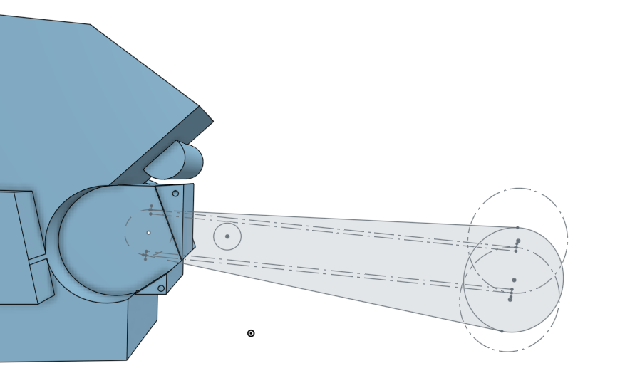
Turns out I had to raise the motor another ~20mm for clearance. Now we know why sportbike motors have transmissions stacked vertically behind the cylinders - high vertical sprocket location relative to motor CoG.
Not half bad for a week's work.
No comments:
Post a Comment
Don't be a dick!