We played the same CoG/geometry game, and found the following:
 |
| Suzi (GS500) Anti-Squat |
 |
| L3na (GSX-R600) Anti-Squat |
Front Suspension
Picking points for the front suspension is similar to the rear - guess, check, adjust, guess again. Tony Foale's software package has a tool called FFE Analysis (which, of course, stands for "Funny Front Ends". Seriously!). Like the anti-squat tool, this package just does the all the arduous trig and weight-transfer math for you, allowing quick design iterations. It also allows you to check things like rake, trail, and to simulate weird head-tube mounting schemes. Super handy.
Unfortunately, when I started looking around the front wheel (before I really began moving suspension points) I discovered I needed more clearance to the radiator - so I ended up moving the motor back 20mm, and increasing the wheel base by 15mm (to 1515). I'll see if I can get that wheelbase back later. Remember - every time I tweak something, I need to re-adjust...everything else.
Anyway, because the front suspension uses two links (as opposed to a single rear swingarm) I can make anti-dive pretty flat:
One behavior you have to watch with this type of suspension is front axle path - if the axle moves forward away from the bike under bump, you're essentially smashing the front tire harder into the bump. You want to minimize forward axle path. You can see how the front wheel moves forward below:
With this design, the wheel moves forward about 15mm over 120mm of suspension travel, as below. Some forward axle path is required for flat-ish anti-dive, but I'll continue trying to minimize it.
Steering
I'll admit to having a rough time trying to figure out some perfect steering scheme. One of the complaints about Hossack front ends is lack of feel, because the bars aren't bolted directly to the top of the fork tubes. I want to minimize the parts count between the upright and my hands. Furthermore, with any type of linkage steering design, you have to compete with a phenomenon called bump-steer: suspension movement causing the suspension to steer.
Typically, Hossack bikes like the BMW Duolever use a butterfly link between the bars, shown below in red:
The links attach to the upright and handlebars with roller bearings; the hinge is a spherical bearing. This way, at straight-ahead steering, there is zero bump steer. Unfortunately, this design only works when the handlebars spin around an axis very close to co-linear with the headtube on the upright. Otherwise, massive bump-steer or binding occurs when you turn the handlebars. Also unfortunately: my rider's hands are nowhere near the steering axis...
I don't want some huge ape-hangar nonsense to get my hands to connect with the steering axis, plus the butterfly link and associated mounting would completely eat all the space up front I could have for mounting things like headlights, turn signals, and wedge plows. I could use a link-to-link type of setup, but more parts = potentially bad feel.
After agonizing about the geometry in play (and a round of phone calls to my brain trust) I realized the best packaging and feel would be satisfied by a tie-rod setup, much like a solid-axle truck front end. My hands would spin a steering spline, rotating a pitman arm, therefore push/pulling a tierod connected to the upright. If only I could minimize bump-steer! So I just went ahead and tried it in CAD to see how good I could get.
Good enough, as it turns out.
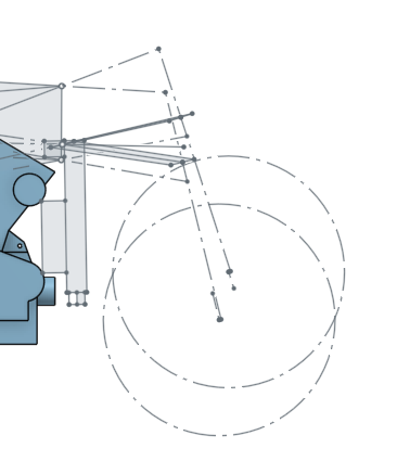
To minimize straight-ahead bump steer, I located my inboard end of the tirod based on guidance from the instant centers of the two control arms. Those are the tips of the spikes drawn below at different suspension positions:
The dotted lines extending out to the instant centers are drawn from a constant place on the upright (where my tierod will mount). Where these dotted axes intersect is about where I want to place the end of my pitman arm to minimize bump-steer when straight ahead. I'll move the inboard point slightly to reduce bump-steer at the mid-corner part of the travel as much as possible (where it's most critical).
To minimize bump-steer when the bars aren't straight, I need to incline the steering spline to the same angle as the headtube. I'll pick an angle which matches the suspension position mid-corner, as usual.
With a pitman arm 50mm long, my straight-ahead bump-steer is ~0.1 degrees; maximum is ~1.5* (@25* of steering input), with left/right imbalanced by ~0.7*.
The suspension points are close enough for me to start modeling the chassis, swingarm, upright, and control arms. I need to do a preliminary design to check to see if anything big has to move again. I'll also need to do some work to figure out how/why I'm mounting my shocks. We'll see what happens this week.


No comments:
Post a Comment
Don't be a dick!